
- Small Oil Pressing Machine - Leader Machinery
- Industrial automatic continuous fryer Soybean Oil Plant
Home> Company News> Design of liquid filling machine
- Address3rd Road, High-tech Zone, Jinan City, Shandong Province
- Factory Address3rd Road, High-tech Zone, Jinan City, Shandong Province
- Worktime9:00--18:00
- Phone(Working Time)086-0531-885125
- Phone(Nonworking Time)086-0531-881256
- Fax086-0531-885125
Design of liquid filling machine
2018-11-09 09:55:26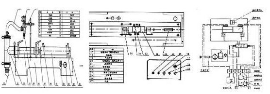
The microwave drying machine equipment company designed is an automatic rotary plastic cup liquid filling machine.
It is mainly used for filling various kinds of beverage such as milk and fruit juice, which is suitable for small beverage manufacturers.
In the design, the intermittent motion of the rotary disc and the coordination of drop cup, filling cup, sealing cup, withdrawing cup and motor are considered.
In packaging machinery, the use of pneumatic technology to achieve automation is quite convenient, effective and applicable. Therefore, the drop cup and withdraw cup movement are mainly realized by pneumatic. Filling automatically flows out of liquid gravity. The intermittent regular movement of the rotary disk is achieved by controlling the stepping motor. The PLC control has the characteristics of simple programming, reliable operation and convenient use, so the whole machine coordinated action is controlled by PLC.
Design of pneumatic circuit
In the pneumatic circuit, the drop Cup circuit requires simple reciprocating motion, and each movement should be completed within the auxiliary working time when the turntable stops. The cup withdrawal loop requires that the cup be lifted first, then the cup is pushed out of the rotary disc and into the conveyor belt. The action of the cup withdrawal loop should also be completed within the auxiliary working time when the rotary disc stops. According to the analysis of working conditions, this system is a low-power system. The design requirement is that the cylinder moves to and fro in a specified time with a small load.
When the cylinder moves, the air consumption is not large, the gravity of the moving parts is small, and there is no special requirement for the reversal. So the drop Cup circuit is controlled by a two-position five-way single-electric control valve. When entering the cup withdrawal loop, it is required to lift the packaged plastic cup from the rotary disc first, and then push it out from the rotary disc (push it to the conveyor belt), so that the sequential action loop controlled by the one-way sequential valve can be selected. According to the design calculation, the working pressure of jacking up cylinder 1 is greater than that of pushing out cylinder 2, and is supplied by the same air compressor. Therefore, in the introduction of cylinder 2 loop should set pressure relief valve, at the same time also need to meet the requirements of adjustable time. In order to maintain a certain push force when the pressure of the feed gas path drops instantaneously, the throttle valve speed regulation and the one-way valve pressure preservation should be connected.
When working, impurities such as moisture, dust and oil in compressed air and fluctuations of output pressure will cause adverse effects on the normal operation of the pneumatic system. Therefore, the primary air source treatment circuit is selected in the pneumatic supply circuit to solve the problems of compressed air purification and stabilization. Because drop Cup circuit and drop Cup circuit share one air pressure source, and the supply pressure P1 and P2 of the two loops are different, high and low pressure control loops should be selected to adjust the air pressure provided by the air pressure source to P1 and P2 2 different pressures.
The compressed air used in the pneumatic system can be directly discharged into the atmosphere, which is the advantage of pneumatics. However, the atomized oil and noise discharged from the exhaust system will cause environmental pollution and must be controlled. We use noise reduction methods in addition to filtration devices in the exhaust circuit to remove oil and install mufflers.
When the determined pneumatic circuits are combined into a pneumatic system that meets the design requirements, the sequence of action among the executing elements should be considered comprehensively, so as to prevent the interference between the transmitting elements and the circuits, reduce the impact and joint pins, and on this basis, reduce the components and improve the efficiency of the system as much as possible.
 Manufacturing plant automatic factory puffed sticky rice cracker production line
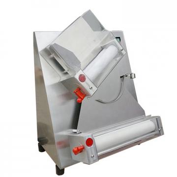 JiaHao machinery PVC Edge Band Sheet Production Line High intensity different color to choose producing PVC edge banging
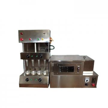 Wholesale products plastic extrusion machine for WPC flooring extrusion line
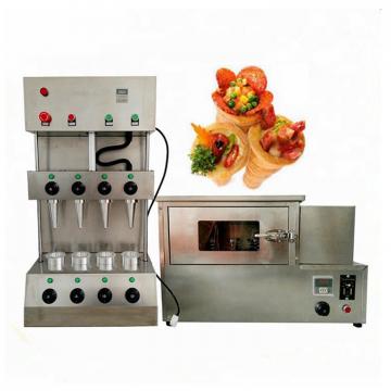
 Best Price Pizza Cone Machine / Pizza Making Machine Production Line
 Factory Supply Dough Divider Cutting Dough Ball Pizza Dough Ball Machine/Bread Production Line